
While some view a wire gauge chart as nothing more than a fundamental engineering concept, we see them as a more in-depth technical topic.
This article is mainly for you DIY-ers who want to build your own solar generator. But, it can also serve as a guide for creating more specific PV system components such as DIY energy storage units/Powerwalls or solar panels wired in series/parallel.
Simply put, a wire gauge refers to an electric wire’s thickness. The size of the wire will determine the following:
- The amount of current (expressed in Amperes) it can carry.
- Its electrical resistance per unit length (expressed in Ohms per foot or meter).
While we understand that some of you may have preferences, we shall use the American Wire Gauge (AWG) format, given that it is more common than Standard Wire Gauge (SWG).
Table of Contents
What is the gauge of a wire?
The gauge of a wire refers to its thickness. It’s measured using the American Wire Gauge (AWG) system, which assigns a number to each gauge size. Basically, the larger the number, the smaller the wire diameter.
So, a wire with a gauge of 14 is thicker than one with a gauge of 18. The thinnest wires have the highest gauge numbers, ranging from 30 to 40, while the thickest wires have the lowest gauge numbers, ranging from 0 to 4/0 (also known as 0000).
Wire gauge is important because it affects how much current the wire can safely carry without overheating or causing a voltage drop. Thicker wires can carry more current and are used for higher-power applications, while thinner wires are used for lower-power applications.
Note to our readers: The American Wire Gauge (AWG) chart is the standard way to determine the thickness of a conductive wire. It’s a standard developed in the United States and helps users decide the appropriate wire size for their specific project.
How to read a wire gauge chart
Being confident in reading wire gauge charts begins with knowing the relationships between each AWG size and its corresponding variables.
The essential associated variables we discuss in this article are:
- Diameter.
- Ampacity (current carrying capacity of the wire.
- Resistance per unit length.
Arguably, it’s essential to discuss each wire gauge’s corresponding weight per unit length, but this is used more on a grid or utility level.
Let’s dissect the wire gauge chart excerpt containing the standard AWG sizes used in a residential setup with that out of the way.
| AWG | Diameter (inches) | Resistance per 1000ft | Ampacity (amperes) |
|---|---|---|---|
| 6 | 0.162 | 0.3951 | 55 |
| 8 | 0.1285 | 0.6282 | 24 |
| 10 | 0.1019 | 0.9989 | 15 |
| 12 | 0.0808 | 2.003 | 9.3 |
| 14 | 0.0641 | 2.525 | 5.9 |
| 20 | 0.032 | 10.15 | 1.5 |
To help you better appreciate this table, let’s convert it into a line graph (see image below) and observe the relationship between the AWG size and the other variables.
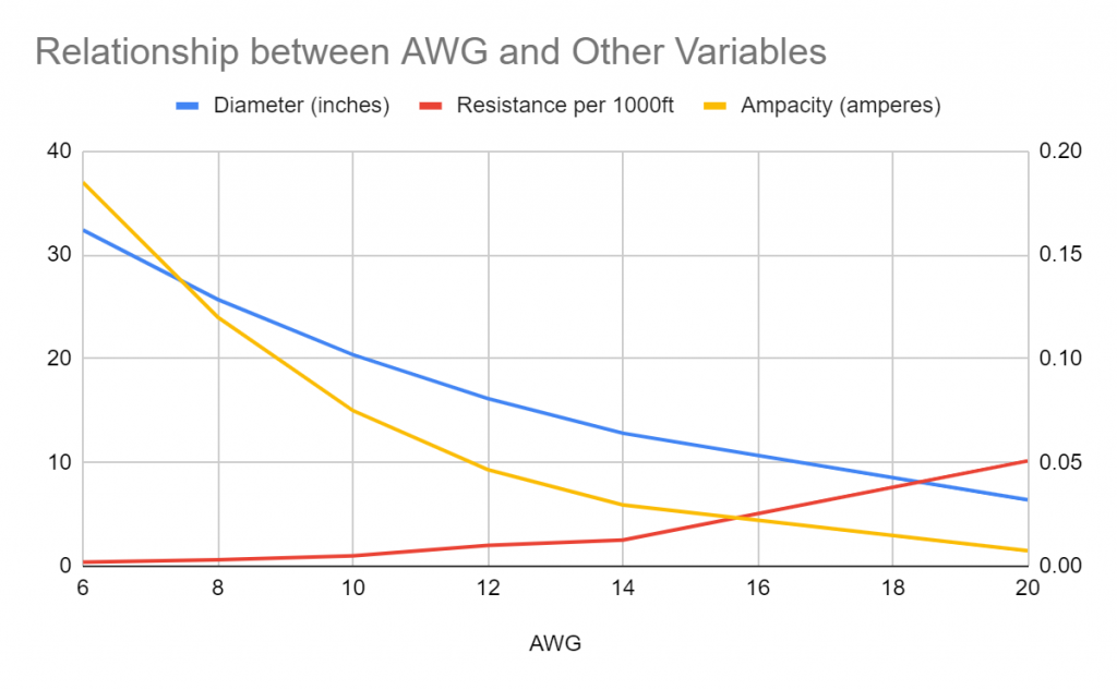
Relationship between AWG size and resistance per 1000ft
Let’s examine the first relationship between AWG size and resistance per 1000 ft.
You’ll notice that the resistance per 1000 ft. (red line) increases as the AWG size increases. Therefore, they have positive covariance, meaning both variables tend to be high or low simultaneously.
However, these two variables don’t have a proportional relationship. This means the ratio of each pair of AWG and Resistance per 1000 ft. aren’t the same.
Relationship between AWG size, diameter, and ampacity
On the other hand, AWG size has a negative covariance relationship with the wire’s diameter (blue line) and ampacity (yellow line).
Not all variables have a proportional relationship with AWG. Size is also vital since you cannot assume the same ratio of each pair of variables to AWG size. This means that you must rely on a wire gauge chart to determine the best wire size for your needs.
Wire gauge chart
There are many variations of wire gauge charts out there, and this table from Solaris-shop.com is our favorite since it balances information and simplicity.
We love it for the following reasons:
- It has both metric and English systems
- Contains essential wire gauge information (resistance and max ampacity)
If it were up to us, we would remove the odd AWG sizes since even ones are more commonly used. This would make the information more practical, concise, and less prone to human errors.
Removing the last column is also a good idea.
Lastly, it’s important to point out that the Maximum Current Rating of the same AWG wire will vary depending on the application. For example, the table below is the AWG wire gauge chart for POWER TRANSMISSION or GRID applications.
Therefore the ratings are lower or more conservative to account for more safety compared to residential applications (see the table after).
| AWG | Diameter (Inches) | Resistance (Ohms/1000ft) | Max Current (Amps) | Max Frequency (100% skin depth) |
|---|---|---|---|---|
| 0000 (4/0) | 0.46 | 0.049 | 302 | 125 Hz |
| 000 (3/0) | 0.4096 | 0.0618 | 239 | 160 Hz |
| 00 (2/0) | 0.3648 | 0.0779 | 190 | 200 Hz |
| 0 (1/0) | 0.3249 | 0.0983 | 150 | 250 Hz |
| 1 | 0.2893 | 0.1239 | 119 | 325 Hz |
| 2 | 0.2576 | 0.1563 | 94 | 410 Hz |
| 3 | 0.2294 | 0.197 | 75 | 500 Hz |
| 4 | 0.2043 | 0.2485 | 60 | 650 Hz |
| 5 | 0.1819 | 0.3133 | 47 | 810 Hz |
| 6 | 0.162 | 0.3951 | 37 | 1100 Hz |
| 7 | 0.1443 | 0.4982 | 30 | 1300 Hz |
| 8 | 0.1285 | 0.6282 | 24 | 1650 Hz |
| 9 | 0.1144 | 0.7921 | 19 | 2050 Hz |
| 10 | 0.1019 | 0.9989 | 15 | 2600 Hz |
| 11 | 0.0907 | 1.26 | 12 | 3200 Hz |
| 12 | 0.0808 | 1.588 | 9.3 | 4150 Hz |
| 13 | 0.072 | 2.003 | 7.4 | 5300 Hz |
| 14 | 0.0641 | 2.525 | 5.9 | 6700 Hz |
| 15 | 0.0571 | 3.184 | 4.7 | 8250 Hz |
| 16 | 0.0508 | 4.016 | 3.7 | 11 kHz |
| 17 | 0.0453 | 5.064 | 2.9 | 13 kHz |
| 18 | 0.0403 | 6.385 | 2.3 | 17 kHz |
| 19 | 0.0359 | 8.051 | 1.8 | 21 kHz |
| 20 | 0.032 | 10.15 | 1.5 | 27 kHz |
| 21 | 0.0285 | 12.8 | 1.2 | 33 kHz |
| 22 | 0.0254 | 16.14 | 0.92 | 42 kHz |
| 23 | 0.0226 | 20.36 | 0.792 | 53 kHz |
| 24 | 0.0201 | 25.67 | 0.577 | 68 kHz |
| 25 | 0.0179 | 32.37 | 0.457 | 85 kHz |
| 26 | 0.0159 | 40.81 | 0.361 | 107 kHz |
| 27 | 0.0142 | 51.47 | 0.288 | 130 kHz |
| 28 | 0.0126 | 64.9 | 0.226 | 170 kHz |
| 29 | 0.0113 | 81.83 | 0.182 | 210 kHz |
| 30 | 0.01 | 103.2 | 0.142 | 270 kHz |
| 31 | 0.0089 | 130.1 | 0.113 | 340 kHz |
| 32 | 0.008 | 164.1 | 0.091 | 430 kHz |
| 33 | 0.0071 | 206.9 | 0.072 | 540 kHz |
| 34 | 0.0063 | 260.9 | 0.056 | 690 kHz |
| 35 | 0.0056 | 329 | 0.044 | 870 kHz |
| 36 | 0.005 | 414.8 | 0.035 | 1100 kHz |
| 37 | 0.0045 | 523.1 | 0.0289 | 1350 kHz |
| 38 | 0.004 | 659.6 | 0.0228 | 1750 kHz |
| 39 | 0.0035 | 831.8 | 0.0175 | 2250 kHz |
| 40 | 0.0031 | 1049 | 0.0137 | 2900 kHz |
What wire gauge do I need?
We already touched on this earlier. But let’s elaborate further to help you determine which wire gauge is best for which application.
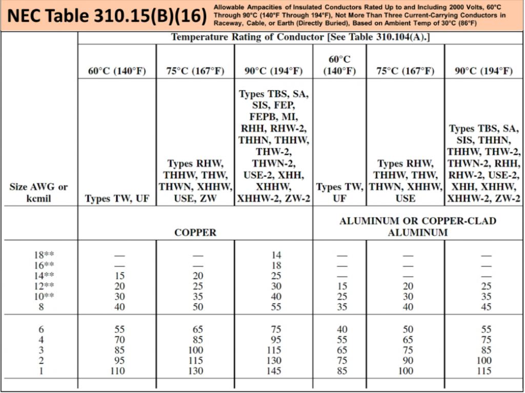
Since we are certain that most of our readers are after a wire gauge chart for residential applications, we will use NEC Table 310.15(B)(16) (see table above) and take a conservative approach.
A conservative approach means taking the lowest rating of each AWG size. For example, the 14-gauge copper wire, according to our NEC table, can accommodate 15 to 25 amperes depending on the conductor temperature rating (140ºF, 167ºF, and 194ºF, respectively).
To err on the side of caution, we’ll stick with the lowest load the 14-gauge copper wire can handle, which is 15 amperes.
So which wire gauge will you most likely need? Generally, 14-gauge and 12-gauge copper wires are commonly used for outlet circuits. It would be best to use AWG 14 wires only in a branch circuit with a 15-ampere capacity or no more than a 1,500-watt demand.
On the other hand, AWG wires with sizes 6, 8, and 10 are for larger appliances such as electric stoves, water heaters, AC units, heat pumps, etc.
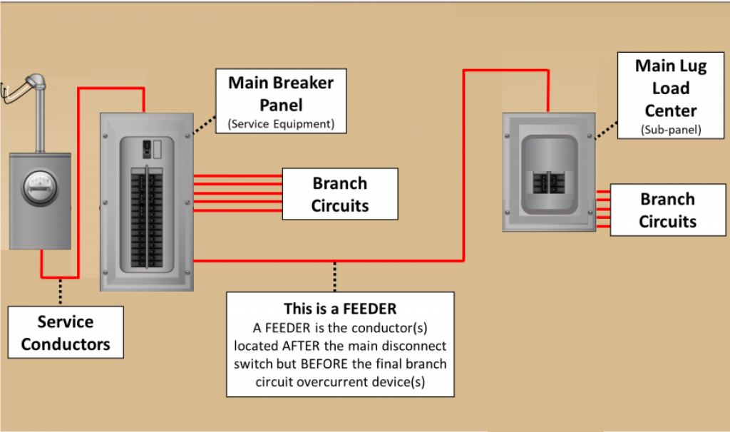
4-gauge wires and below are more suitable for feeders depending on your load. The wires or conductor should not be smaller than AWG 8 copper wire for service conductors.
The bottom line
Residential wiring projects all adhere to the National Electric Code of the United States. If you are not sure about the conductor temperature rating of your wire, we recommend using conservative ampacity ratings to avoid potential problems such as overheating and fires.
Avoid aluminum wire
While aluminum wiring is not illegal to use in a residential setting, we highly recommend that you steer clear of it except for specific applications.
Some examples include residential service entrance wiring and single-purpose higher amperage circuits such as 240-volt air conditioning or electric range circuits.
How do you determine wire gauge?
Knowing how to determine a wire gauge without the help of a wire gauge chart is unnecessary. In all seriousness, wire gauge charts of different formats are highly accessible in our modern age through the internet.
However, in the event that you find yourself in a pickle, here’s how a handyman (or woman) would handle it:
Please note: Determining a wire gauge is possible without a chart only if you can access alternative references, such as a wire gauge tool. However, wire gauge tools are not suitable for gauging stranded wires.
- Use a wire-stripping tool to remove the cable insulation.
- Determine whether your wire is solid or stranded.
- Gauging solid wires.
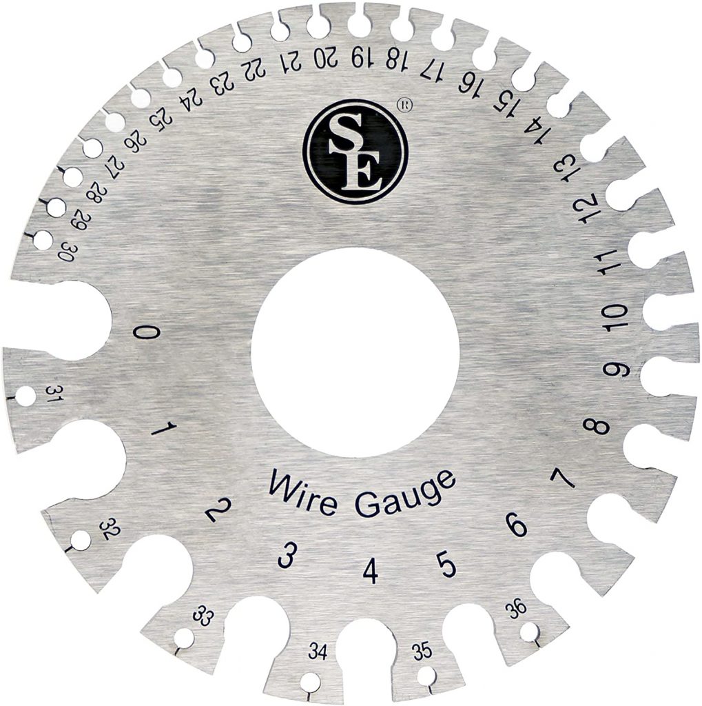
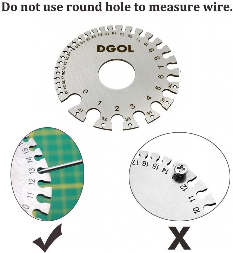
- Use a wire gauging tool.
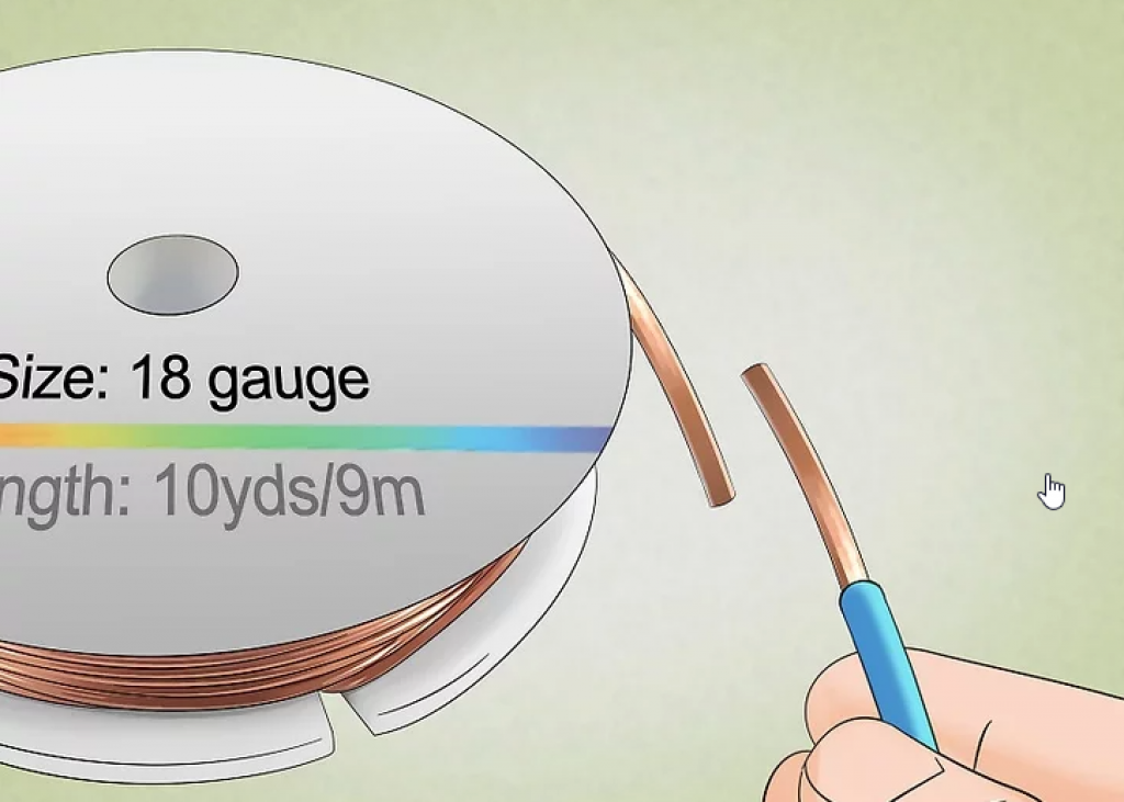
- Compare the wire to another wire with a measured gauge.
- Gauging stranded wires.
- Measure the diameter of a single wire strand.
- Use the CMA formula (Diameter2 multiplied by # of strands).
- Find the CMA’s corresponding AWG size.
Step 1: Use a wire-stripping tool to remove the cable insulation
The first step you need to carry out when determining a wire gauge is stripping the cable. Maybe it’s just us, but we find wire stripping using a decent wire stripper or crimper to be very satisfying.
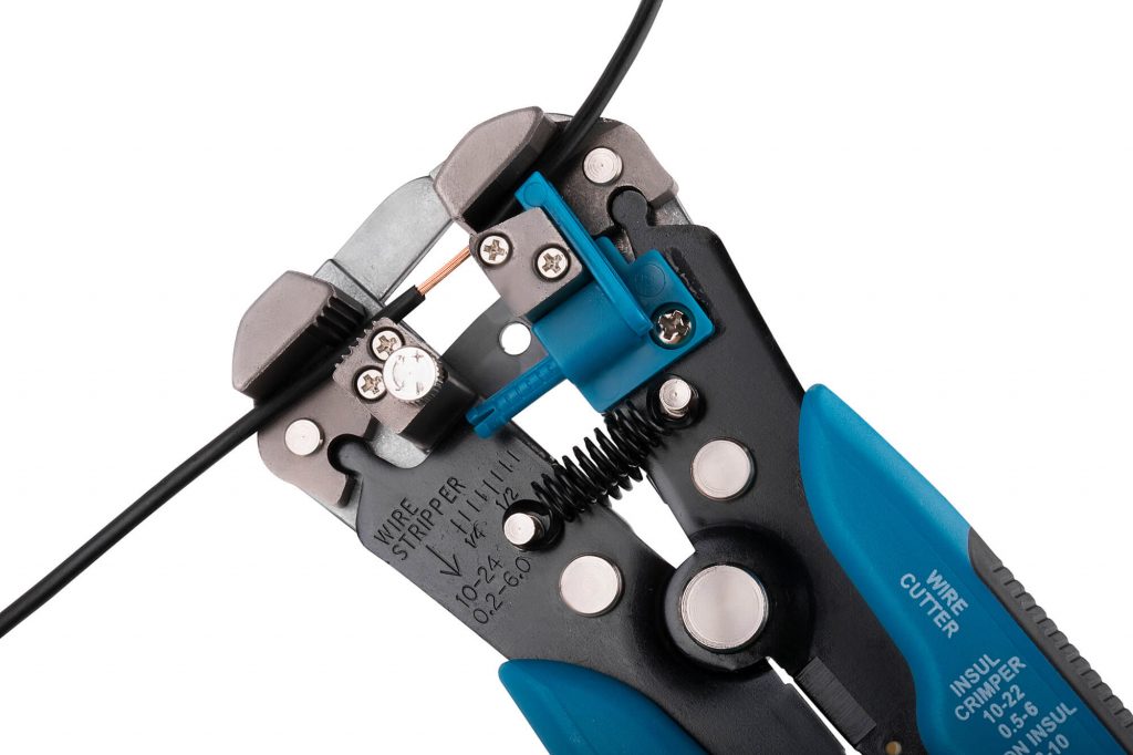
Source: Capri Tools
View on Amazon
Step 2: Determine whether your wire is solid or stranded
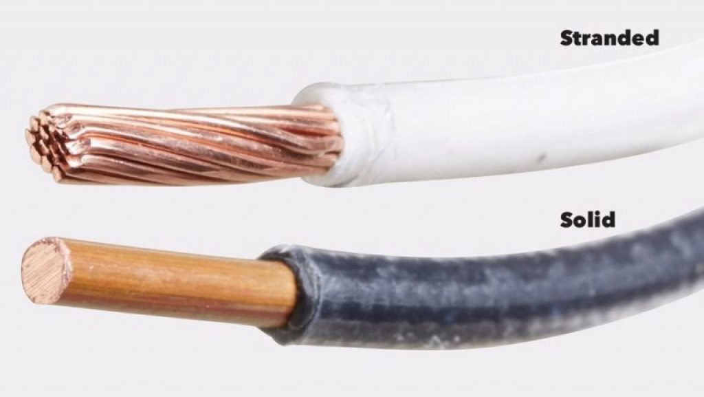
Source: cssciencecenter.org
Once you’ve removed the insulation, determine whether your wire is solid or stranded. Then, follow the corresponding steps depending on the type you have.
Step 3.1: Gauging solid wires
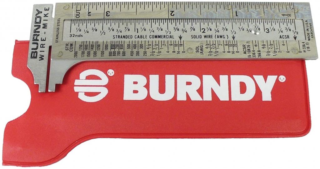
3.1.1 Use a wire gauging tool
A wire gauging tool is around measuring device used to confirm the diameter of a wire. Using it is pretty straightforward. Just insert the wire in the gaps (not the round holes) to see the AWG size of your wire.
3.1.2 Compare the wire to another wire with a measured gauge
You can eyeball it and compare your wire to a marked one as an alternative. You can do this if you have spare labeled cables lying in your garage. Going to your local hardware store is also an option.
However, we believe this method should be considered a last resort. We recommend consulting your seller before considering this alternative.
Source: Wikihow
Step 3.2: Gauging stranded wires
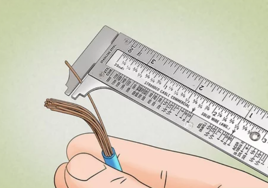
3.2.1 Measure the diameter of a single wire strand
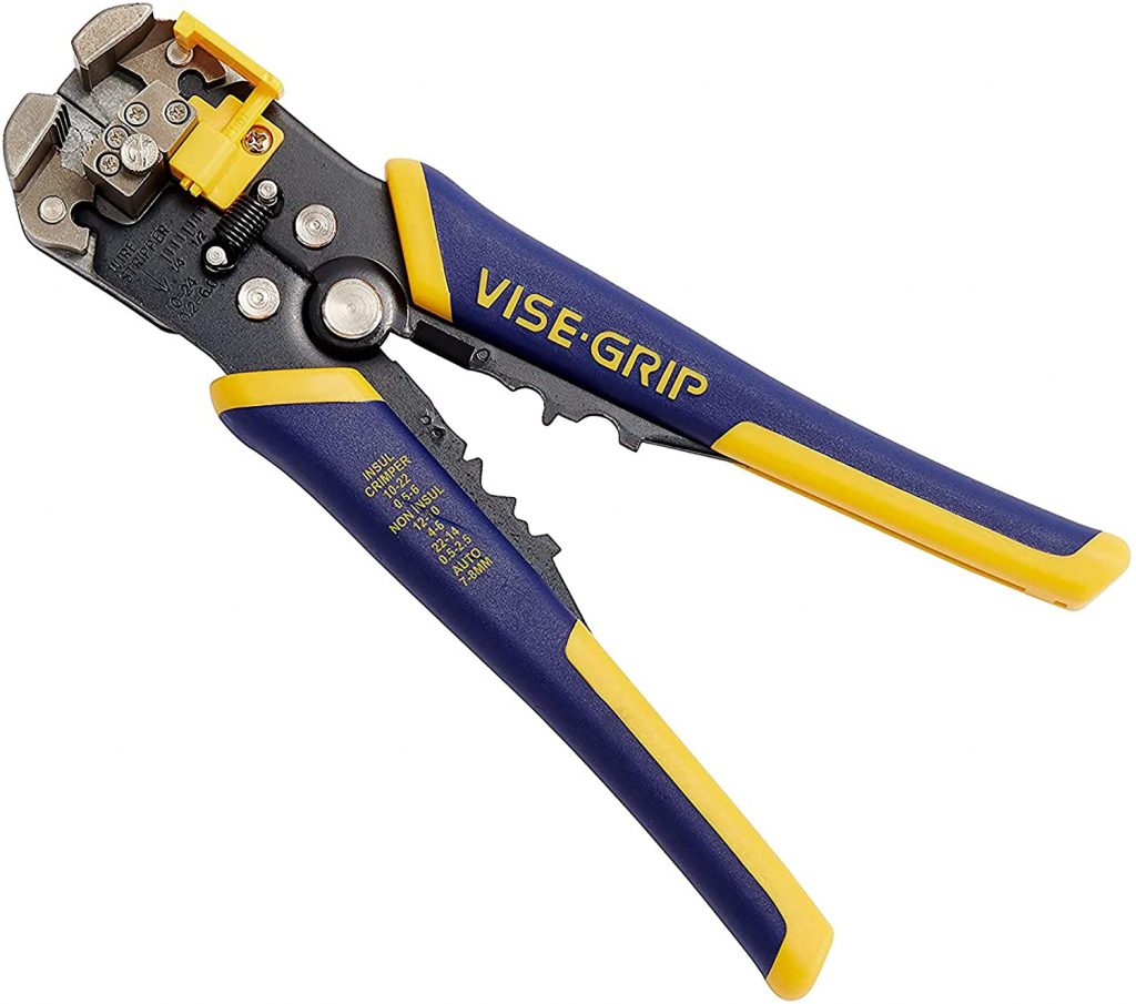
In the case of stranded wires, you might need to purchase another measuring tool to accurately measure individual strand diameters (see image below).
View on Amazon
Source: Wikihow
3.2.2 Use the CMA formula (diameter2 multiplied by # of strands)
Once you have your strand diameter, you’ll use the Circular MIL Area (CMA) formula to determine the Stranded Wire AWG.
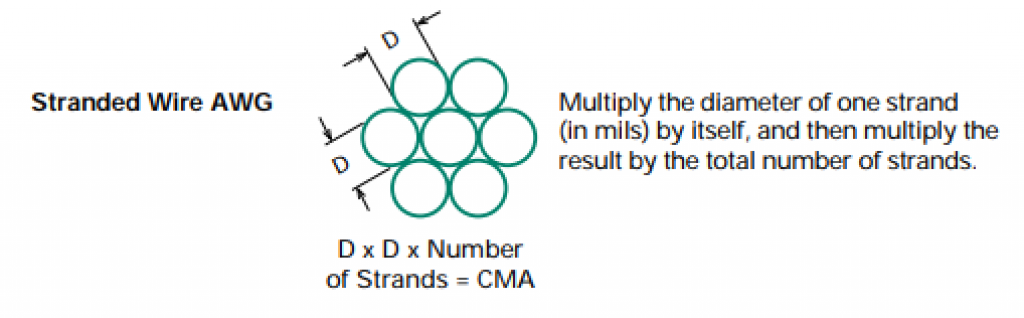
Source: Zierick.com
The CMA formula can be expressed as (Wire Diameter)2 multiplied by # of wire strands (see image above).
3.2.3 Find the CMA’s corresponding AWG size
Once you get the CMA, look for its corresponding AWG size in this wire gauge chart.
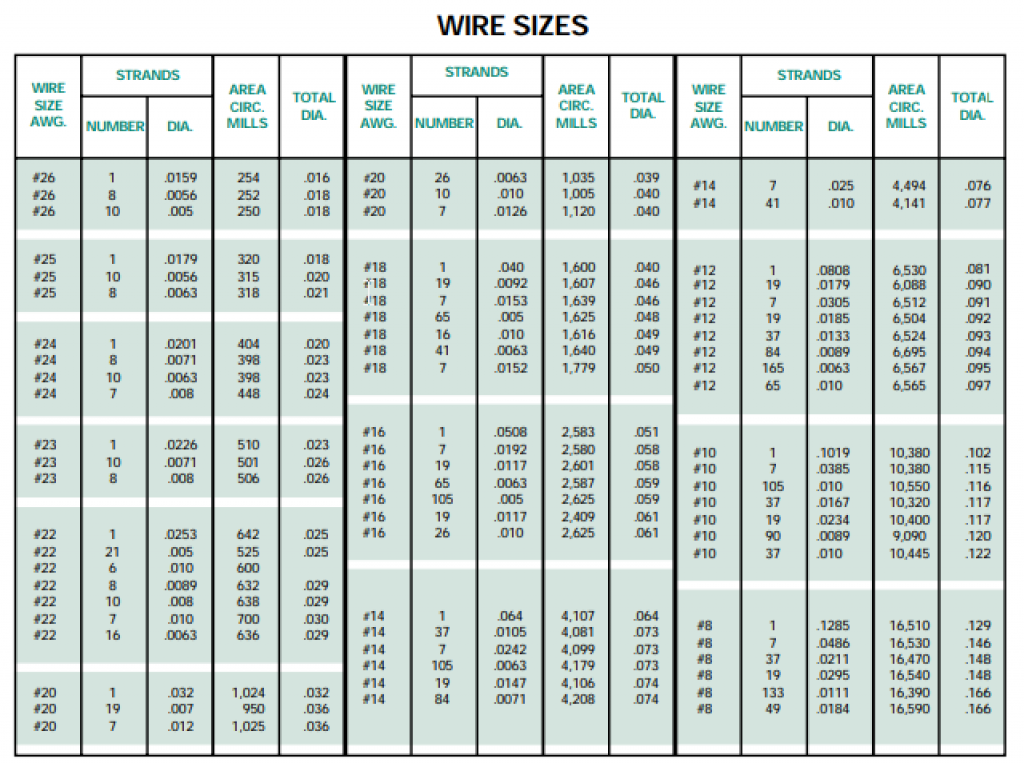
Source: Zierick.com
Does wire gauge affect amps?
Yes. As seen in our line chart before, AWG size has a negative covariance relationship with the wire’s diameter (blue line) and ampacity (yellow line).
This means that wires with smaller AWG sizes shall have thicker wire diameters and vice versa. Thicker wires carry more current.
To help you remember this relationship, we can compare this concept to our water pipes. The wire is your pipe, and the current is the amount of water flowing through the pipes.
Water pipes with bigger diameters can carry more water at any given time. This concept applies to the wire and ampacity too.
The bottom line
Wire gauge affects ampacity. Smaller AWG size means larger diameters and more current carrying capacity.
What happens if I use a larger gauge than required?
To be clear, “using a larger wire gauge” means you are oversizing your wire’s ampacity.
Going with more ampacity will not carry severe consequences. It’ll cost more and probably require adjustments to the wire’s physical pathways (more ampacity means thicker wires).
But there are perks to using larger gauges. Wires with larger diameters stay cooler due to low resistance. As you all know by now, the overall resistance per unit length decreases as the wire diameter increases. This means less power dissipation across your wire.
The power dissipation formula can be expressed as:
Current2 multiplied by resistance (P= I2 x R).
The power dissipated across the wire causes it to heat up, which means electric energy is lost as heat energy every second.
Lastly, using a larger gauge AWG wire offers you more allowance to draw more current should you need it in the future.
Bottom line
Using thicker wires with higher ampacity costs more and requires bigger pathways. However, they translate to lower resistance, less heat loss, and more electricity savings. You can also accommodate more electric demand in the future without overhauling your wiring system.
Does the wire gauge affect your electricity bill?
Yes, as seen in our line chart before, AWG size has a positive covariance relationship with resistance per unit length.
Small AWG numbers have smaller resistances, saving you more money due to less power dissipation.
Remember: Using wires that are the appropriate size for the electrical load can help ensure that your appliances and devices receive the proper amount of power, which can help optimize their performance and reduce energy consumption.
FAQs
Can I use a wire gauge that is not in accordance with the American Wire Gauge (AWG) system?
Yes, you can use wire gauges that are not part of the AWG system, such as those measured in Standard Wire Gauge (SWG).
However, it is crucial to convert the measurements accurately to ensure the safety and efficiency of the electrical system, as using incorrect wire sizes can lead to overheating and potential fire hazards.
How does the length of the wire impact its overall resistance and performance in an electrical circuit?
The length of the wire directly impacts its resistance; the longer the wire, the higher the resistance. This increased resistance can lead to a voltage drop across the wire, affecting the performance of electrical devices connected to it.
It is essential to consider both the length and gauge of the wire when designing an electrical circuit to ensure optimal performance and safety.
Is there any difference in the wire gauge requirements for AC (Alternating Current) and DC (Direct Current) applications?
Yes, AC and DC applications may have different wire gauge requirements due to the differences in how they transmit energy.
AC currents can induce electromagnetic fields and may require wires with additional insulation or shielding, especially in high-frequency applications, to prevent interference with other electronic devices.
Proper wire gauge and type should be selected based on the specific requirements of the application, considering factors like current type, voltage, and load.
How does ambient temperature affect the selection of wire gauge?
Ambient temperature can significantly impact the selection of wire gauge. Higher temperatures can increase the resistance of the wire and reduce its current-carrying capacity.
In environments with high ambient temperatures, it may be necessary to use wires with larger diameters or special insulation to maintain performance and prevent overheating and potential fire hazards.
Can the color of the wire insulation be used to determine the wire gauge?
No, the color of the wire insulation does not determine the wire gauge. The color-coding of wires is typically used to identify the purpose of the wire in electrical circuits, such as which one is the live, neutral, or ground wire.
To determine the wire gauge, one must refer to wire gauge charts or use a wire gauging tool.
Is it safe to use aluminum wires instead of copper for residential wiring, given the proper gauge is selected?
While it is technically legal to use aluminum wiring, it is generally not recommended for most residential applications due to its lower conductivity and higher resistance compared to copper. Aluminum wires need to be larger in diameter than copper wires to carry the same amount of current safely.
Additionally, aluminum can oxidize and corrode over time, leading to poor connections and increased fire risk. If aluminum wiring is used, special precautions, connectors, and installation methods are required to ensure safety.
Final thoughts
The use of electricity in the home has risen sharply since the 1930s. Therefore it makes sense to regularly check the adequacy of your existing wires to accommodate current.
And while we did touch on the basic stuff on wire gauge charts, there are more factors to consider when handling electricity during home improvements.
We apologize for making you feel anxious in some parts of this article. We didn’t put them there to scare you. Instead, we brought them up to inform you about electricity’s inherent safety risks and hazards.
That being said, this last section is included to help impart advanced knowledge and keep you safe altogether.
Safety first
While we touched on the basics of AWG wires in this article, we encourage our readers to consult with professionals when dealing with electricity. It’s no secret that electric power poses severe hazards; hence, it shouldn’t be taken lightly.
Therefore, we suggest that you limit your DIY activities to low-power projects. Tinkering with main breaker panels, service conductors, feeders, branch circuits, and similar electrical components (see image below) must comply with NEC standards.
Source: Mr. Dennis Bordeaux